Differential gaging usually refers to the process of using two sensing devices and combining the results into one measurement. The measured dimension is the change in the position of the two sensing components.
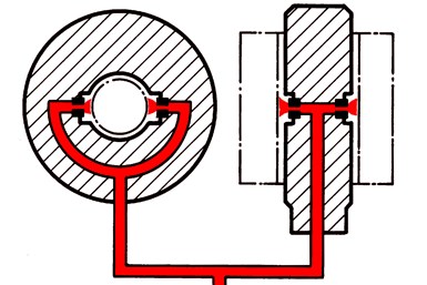
I’ve noted previously that differential gaging has some advantages over comparative measurements using a single, sensing head against a fixed, reference surface. One such advantage is the ability to measure size without regard to position (see Fig. 1). When the two gage heads are in line and in an opposed position, the sensed dimension will be the change in the separation of the two gage tips: in this case, the size of the part.
When measuring in this manner, the staging of the part does not become part of the measurement loop. The platen in a differential system simply places the part between transducers. With a single-head system, the platen is part of the measurement loop, and therefore flatness and configuration of the platen is critical.
There are a number of different measuring systems available that can provide differential gaging, including air and electronic gaging. Air gaging is probably the most common, since every two-jet air plug and air ring utilizes the differential gaging principle. Most air gages measure back-pressure that builds up in the system when the tooling is placed in close proximity to a workpiece. This results in higher air pressure, which the gage comparator converts into a dimensional value. Thus, as the plug fits into the part, it is the combination of both jets that represents the diameter of the part — without regard to where in the part the plug happens to be.
The same is true with electronic probes. In this case however, the probes are combined electronically to provide the differential measurement.
Moving a step further, we can now take this differential gaging (as seen with the air plug or a pair of electronic probes) and combine these circuits or channels differentially — a different differential. This differential gaging using either air or electronic probes can be deployed in a variety of applications, including measurement of angle on tapers and shafts without regard to the part dimensions. Also, concentricity of two shaft diameters, match gaging, squareness or checking parallelism of a workpiece and its support surface are all applications of this technique.
The distinctions between the two circuits for most of these differential applications is the result of the measurement that is being looked for. Take for example the match gage application. One differential circuit is measuring the OD while the other circuit is measuring the ID. If both diameters are zeroed on their masters, the system will conveniently show the clearance or interference between the two parts, basically comparing one diameter to another.
Read more: Differential Gaging: 2 Big Benefits for In-Process Part Control


