Surface plates provide a large, flat reference surface that can be extremely useful for inspecting incoming, in-process or finished parts. The surface plate is often referred to as the foundation of measurement since it provides the reference for much of the layout work done in an inspection cell. When used in combination with various gages and accessories, such as height gages, gage blocks, angle plates and squares, they can be used to check a wide range of parameters, including length, flatness, squareness, straightness, angle, feature location and runout. Surface plates are simple and extremely versatile.
Surface plates provide a stable reference surface on a large scale, making a great many gaging setups possible on a single, simple piece of equipment. When a gaging application does not warrant the purchase of a special-purpose fixture gage, surface plates can provide an economical, all-purpose solution. Surface plates also come in many sizes, making them usable for a wide range of part sizes.
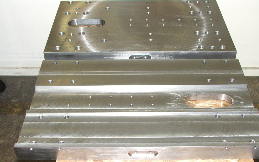
However, users may not realize that the surface plate can become a gage. A hole can be bored in the plate and a gage head installed to inspect flush surfaces for flatness without the use of a height stand. When small parts are involved, inspection can be done by simply moving a part over the probe and reading the flatness variations directly on the amplifier readout. What is happening here is that the three highest points on the surface plate are creating a plane on which the part rides. The probe mounted in the plate then senses the change or variation in the surface of the part as it is moved over it. This is a dynamic check in that the part must move to determine the out-of-flatness condition, so, rather than have an operator try to remember the highest and lowest value on the display and figure out the difference — which is the total out-of-flatness condition — the amplifier would be set to its dynamic TIR (max-min) mode, and the result would be the out-of-flatness condition.
Of course, an “assumption” must be made with this form of flatness check. Note that, in this example, there is one electronic probe the part is moved over it. Thus, there is no way that every square millimeter of the part could ever be explored. What generally happens is that the operator will follow a pattern on the part that covers the outer and inner area. The user then “assumes” everything in between is within what was measured. That is usually the case, but some areas may be missed. Nevertheless, for a fast and high-performance check, this type of flatness gage cannot be beat.
Speaking of high performance — and again this is a relative term — surface plates come in many grades, and the grade will help determine the performance of the system. Three-point support provided on a surface plate may have an accuracy to 50μ” (inspection grade A). Other plate sizes and accuracies are available. This must be considered as part of the measurement’s potential error.
To take the gage concept one step further, a second gage head mounted in an arm/stand configuration can be positioned directly above the one embedded in the surface plate, permitting independent measurements of flatness, thickness and parallelism. For relatively small parts, it is fairly easy to move the part between the probes to get readings of flatness and parallelism. The thickness check might be made either at the beginning or end of the dynamics and used as the nominal thickness, with the parallelism result applied to this. With so many things going on and the need to share probes, it becomes a little more complicated for the operator.
Read more: How to Make a Surface Plate Into a Gage


